pyyeti.nastran.bulk.wtrspline_rings
- pyyeti.nastran.bulk.wtrspline_rings(f, r1grids, r2grids, node_id0, rspline_id0, rbe2_id0=None, cord_id=None, makeplot='new', DoL='0.1', independent='ring1')[source]
Creates a smooth RSPLINE to connect two rings of grids
- Parameters:
f (string or file_like or 1 or None) – Either a name of a file, or is a file_like object as returned by
open()orio.StringIO. Input as integer 1 to write to stdout. Can also be the name of a directory or None; in these cases, a GUI is opened for file selection.r1grids (2d array_like or DataFrame or tuple) – Ignoring the tuple input option for now, r1grids contains the ids and locations of the ring 1 grids in basic coordinates. If 2d array_like, it has 4 columns describing the ring 1 grids:
[id, x, y, z] < -- basic coordinates
If DataFrame, it is assumed to be the USET DataFrame containing just the ring 1 grids. The format of this DataFrame is described in
pyyeti.nastran.op2.OP2.rdn2cop2().The default name in the output comments for ring 1 is ‘Ring 1’. By using the tuple input option, you can provide a name. For example, the default is equivalent to:
('Ring 1', r1grids)
Note
Note that when using a USET table, the grids can be defined in any local coordinate system(s). However, both r1grids and r2grids must use the same basic coordinate system.
r2grids (2d array_like or DataFrame or tuple) – Contains the ids and locations (and optionally, the name) of the ring 2 grids in basic coordinates. See r1grids for description of format. The default name for ring 2 is ‘Ring 2’.
node_id0 (integer) – 1st id of new nodes created to ‘move’ ring 1 nodes
rspline_id0 (integer) – 1st id of RSPLINEs
rbe2_id0 (integer or None; optional) – 1st id of RBE2 elements that will connect old ring 1 nodes to new ones. If None,
rbe2_id0 = node_id0.cord_id (integer or None; optional) – ID for the local coordinate system for the r1grids. If None, it is set to
node_id0 * 10.makeplot (string or axes object; optional) – Specifies if and how to plot data showing the RSPLINE.
makeplot
Description
‘no’
do not plot
‘clear’
plot after clearing figure
‘add’
plot without clearing figure
‘new’
plot in new figure
axes object
plot in given axes (like ‘add’)
Note that if makeplot is ‘add’ or an axes object, it must be 3d; otherwise a ValueError exception is raised.
DoL (string or real scalar; optional) – Specifies ratio of diameter of elastic tybe to the sum of the lengths of all segments. Written with:
f'{DoL:<8}'independent (str; optional) – Either ‘ring1’ or ‘ring2’ or the assigned name if one was provided in the r1grids or r2grids input. This input is case-insensitive and all spaces are ignored, so ‘Ring 1’ is the same as ‘ring1’. Specifies which ring will be independent on the RSPLINEs. Note that is different than just switching the order of r1grids and r2grids. This option modifies step 4 below while switching r1grids and r2grids modifies all the steps.
- Returns:
None
Notes
This routine writes GRID, RBE2 and RSPLINE lines to the output file.
The approach is as follows (N = number of ring 1 grids):
Fit a circle through both the ring 1 nodes and the ring 2 nodes. A new “ring 1” local coordinate system is defined (see
pyyeti.ytools.fit_circle_3d()) to simplify the creation of the new RSPLINE. In the local system, z is perpendicular to the plane of the circle and x is aligned with node 1 of ring 1.Create N new ring 1 grids at station and radius of ring 2 grids, but at the same angular location as original N.
RBE2 these new grids to the N original grids. The new grids are independent.
Write RSPLINE cards using
wtrspline(). The first RSPLINE starts at the independent grid (on ring 1 or ring 2 according to independent) with the lowest angular location. The angular locations range from 0 to 360 degrees, counter-clockwise. The RSPLINEs proceed counter-clockwise around the circle.
See also
- Raises:
ValueError – When the perpendicular directions of r1grids and r2grids do not match within tolerance: absolute value of the cosine of the angle between the two perpendicular directions must be > 0.99. When a r1grids or r2grids DataFrame does not have a multiple of 6 rows. When the makeplot option tries to add to an axes object that is not using a 3d projection.
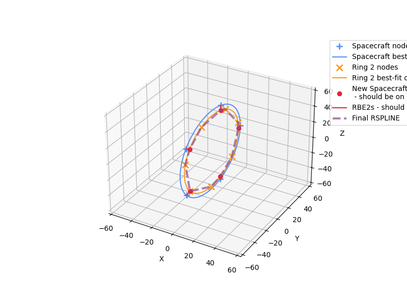
Examples
Define two rings of grids:
Ring 1 will be at station 0.0 with 5 nodes on ring of radius 50. IDs will be 1 to 5.
Ring 2 will be at station 1.0 with 7 nodes on ring of radius 45. IDs will be 101 to 107.
For demonstration, ring 1 will be named ‘Spacecraft’ while the default will be accepted for ring 2 (which is ‘Ring 2’).
>>> import numpy as np
>>> import matplotlib.pyplot as plt
>>> from pyyeti import nastran
>>> theta1 = np.arange(0, 359, 360/5)*np.pi/180
>>> rad1 = 50.
>>> sta1 = 0.
>>> n1 = len(theta1)
>>> ring1 = np.vstack((np.arange(1, n1+1),      # ID
...                    sta1*np.ones(n1),        # x
...                    rad1*np.cos(theta1),     # y
...                    rad1*np.sin(theta1))).T  # z
>>> # Provide a name for ring 1:
>>> ring1 = ('Spacecraft', ring1)
>>> theta2 = np.arange(10, 359, 360/7)*np.pi/180
>>> rad2 = 45.
>>> sta2 = 1.
>>> n2 = len(theta2)
>>> ring2 = np.vstack((np.arange(1, n2+1)+100,  # ID
...                    sta2*np.ones(n2),        # x
...                    rad2*np.cos(theta2),     # y
...                    rad2*np.sin(theta2))).T  # z
>>> fig = plt.figure('Example', figsize=(8, 6))
>>> fig.clf()
>>> ax = fig.add_subplot(1, 1, 1, projection='3d')
>>> nastran.wtrspline_rings(
...     1, ring1, ring2, 1001, 2001,
...     makeplot=ax)
$
$ Fit of Spacecraft grids:
$     Center: [0.000, 0.000, 0.000] (in basic)
$     Radius: 50.0
$
$ Fit of Ring 2 grids:
$     Center: [1.000, -1.776e-15, -3.553e-15] (in basic)
$     Radius: 45.0
$
$ Origin of local CORD2R 10010 is at center of Spacecraft; z is
$ perpendicular to plane of circle, and x is aligned with node 1 (and
$ new node 1001).
$
$ Coordinate 10010:
CORD2R*            10010               0  0.00000000e+00  0.00000000e+00*
*         0.00000000e+00  1.00000000e+00  0.00000000e+00  0.00000000e+00*
*         0.00000000e+00  1.00000000e+00  0.00000000e+00
$
$ Grids to RBE2 to the Spacecraft grids. These grids line up with the
$ Ring 2 circle so that the RSPLINE (which ties together these new grids
$ and the Ring 2 grids) will be smooth.
$
GRID*               1001           10010     45.00000000     -0.00000000
*             1.00000000               0
GRID*               1002           10010     13.90576475     42.79754323
*             1.00000000               0
GRID*               1003           10010    -36.40576475     26.45033635
*             1.00000000               0
GRID*               1004           10010    -36.40576475    -26.45033635
*             1.00000000               0
GRID*               1005           10010     13.90576475    -42.79754323
*             1.00000000               0
$
$ RBE2 the Spacecraft nodes to new nodes created above (the new nodes
$ are independent):
$
RBE2,1001,1001,123456,1
RBE2,1002,1002,123456,2
RBE2,1003,1003,123456,3
RBE2,1004,1004,123456,4
RBE2,1005,1005,123456,5
$
$ RSPLINE the Ring 2 nodes to the new nodes created above, with the new
$ nodes being independent.
$
RSPLINE     2001     0.1    1001     101  123456     102  123456    1002
RSPLINE     2002     0.1    1002     103  123456    1003
RSPLINE     2003     0.1    1003     104  123456     105  123456    1004
RSPLINE     2004     0.1    1004     106  123456    1005
RSPLINE     2005     0.1    1005     107  123456    1001